El reloj que he utilizado es el DS1307 un integrado capaz de mantener la hora, fecha, el calendario discrminando los meses de 30 o 31 días, años bisiestos, etc, es capaz de mantener la hora sincronizada durante años sin la alimentación principal y sólo con una pila de botón.
 Integra además un bus de comunicaciones serie I2C para comunicarse con el microcontrolador mediante sólo dos cables, ahorrando así puertos de entrada/salida para poder usarlos luego para sensores.
 La conexión es muy sencilla, sólo dos lineas de datos y los cables de alimentación, el pin7 puede dejarse desconectado, se utiliza para generar una onda cuadrada de frecuencia seleccionable pero en este montaje no la voy a utilizar.
Cuando hice el montaje de prueba, como era tan sencillo lo monté directamente soldado sobre una placa de prototipos y me encontré con un problema totalmente inesperado, el DS1307 se calentaba...
No era capaz de encontrar el problema, precisamente porque era un montaje tan sencillo sólo se me ocurría pensar que era el propio integrado el que debía estar mal, ya que había revisado todas las conexiones y no había ningún corto ni conexión errónea.
Cambié el integrado y pasaba lo mismo, también se calentaba.
Decidí hace otro montaje en una placa breadboard y funcionó perfectamente, no se calentaba nada y me di cuenta de que las resistencias de pull-up que estaba utilizando eran la causa del problema.

Nunca le había dado demasiada importancia, siempre utilizaba las que tuviera por allí a mano, de 2K2, de 4K, más o menos de ese orden y nunca tuve problema.
En este montaje he aprendido que no da igual, con resistencias pull-up de 4K7 se calentaba y con las de 10K que utilicé después, no se calentaba.
Así que las resistencias de pull-up tienen su importancia, no vale cualquier valor, aunque en el data-sheet http://www.sparkfun.com/datasheets/ Components/DS1307.pdf no viene muy bien explicado...
En el esquema de conexionado de la derecha, la pila representada se sustituye por una de botón de 3V, en el fritzing no había y tuve que poner esa batería de 3V para ilustrar el montaje.
Voy a preparar una carpeta compartida y dejaré en ella el archivo de fritzing de la imagen de arriba para poder verlo y modificarlo mejor.
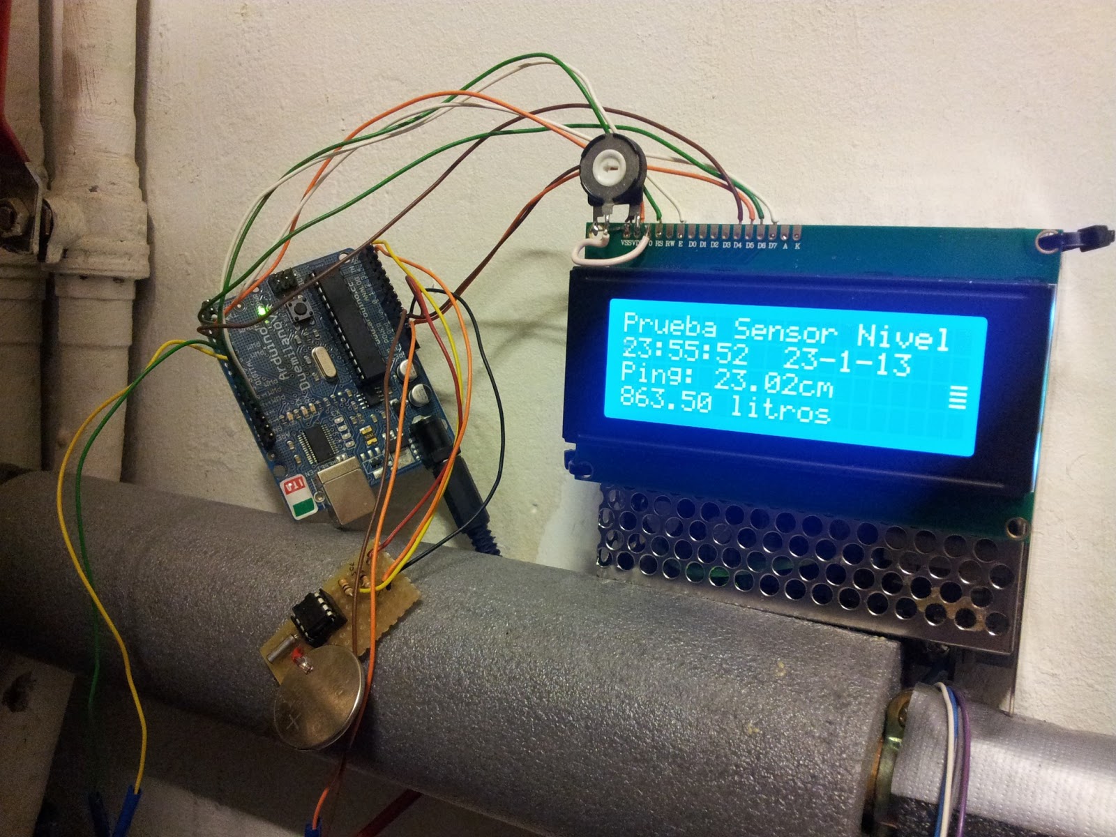
Una vez funcionando e integrado en el sistema, ya tenemos lectura en la pantalla LCD de hora, fecha y nivel de combustible, va a estar funcionando unos días hasta que tenga tiempo de poner a funcionar la tarjeta SD y registrar los datos.
Aquí el código, por ahora no está muy depurado y es una mezcla de los códigos que tenía funcionando, el del nivel de combustible, del LCD y el del reloj:
//
// Maurice Ribble
// 4-17-2008
// http://www.glacialwanderer.com/hobbyrobotics
/* The circuit:
 * LCD RS pin to digital pin 12
 * LCD Enable pin to digital pin 11
 * LCD D4 pin to digital pin 5
 * LCD D5 pin to digital pin 4
 * LCD D6 pin to digital pin 3
 * LCD D7 pin to digital pin 2
 * LCD R/W pin to ground
 * 10K resistor:
 * ends to +5V and ground
 * wiper to LCD VO pin (pin 3)

 Library originally added 18 Apr 2008
 by David A. Mellis
 library modified 5 Jul 2009
 by Limor Fried (http://www.ladyada.net)
 example added 9 Jul 2009
 by Tom Igoe
 modified 22 Nov 2010
 by Tom Igoe

 This example code is in the public domain.

 http://arduino.cc/en/Tutorial/LiquidCrystalDisplay

 */


// This code tests the DS1307 Real Time clock on the Arduino board.
// The ds1307 works in binary coded decimal or BCD.  You can look up
// bcd in google if you aren't familior with it.  There can output
// a square wave, but I don't expose that in this code.  See the
// ds1307 for it's full capabilities.
// scl conectado a pin analog5
// sda concetado a pin analog4
// include the library code:
#include <LiquidCrystal.h>
#include <NewPing.h>
#include "Wire.h"
// initialize the library with the numbers of the interface pins
LiquidCrystal lcd(12, 11, 5, 4, 3, 2);
#define TRIGGER_PIN  7  // Arduino pin tied to trigger pin on the ultrasonic sensor.
#define ECHO_PIN     6  // Arduino pin tied to echo pin on the ultrasonic sensor.
#define MAX_DISTANCE 150 // Maximum distance we want to ping for (in centimeters). Maximum sensor distance is rated at 400-500cm.
#define DS1307_I2C_ADDRESS 0x68

NewPing sonar(TRIGGER_PIN, ECHO_PIN, MAX_DISTANCE); // NewPing setup of pins and maximum distance.

// Convert normal decimal numbers to binary coded decimal
byte decToBcd(byte val)
{
  return ( (val/10*16) + (val%10) );
}

// Convert binary coded decimal to normal decimal numbers
byte bcdToDec(byte val)
{
  return ( (val/16*10) + (val%16) );
}

// Stops the DS1307, but it has the side effect of setting seconds to 0
// Probably only want to use this for testing
/*void stopDs1307()
 {
 Wire.beginTransmission(DS1307_I2C_ADDRESS);
 Wire.write(0);
 Wire.write(0x80);
 Wire.endTransmission();
 }*/

// 1) Sets the date and time on the ds1307
// 2) Starts the clock
// 3) Sets hour mode to 24 hour clock
// Assumes you're passing in valid numbers
void setDateDs1307(byte second,        // 0-59
byte minute,        // 0-59
byte hour,          // 1-23
byte dayOfWeek,     // 1-7
byte dayOfMonth,    // 1-28/29/30/31
byte month,         // 1-12
byte year)          // 0-99
{
  Wire.beginTransmission(DS1307_I2C_ADDRESS);
  Wire.write(0);
  Wire.write(decToBcd(second));    // 0 to bit 7 starts the clock
  Wire.write(decToBcd(minute));
  Wire.write(decToBcd(hour));      // If you want 12 hour am/pm you need to set
  // bit 6 (also need to change readDateDs1307)
  Wire.write(decToBcd(dayOfWeek));
  Wire.write(decToBcd(dayOfMonth));
  Wire.write(decToBcd(month));
  Wire.write(decToBcd(year));
  Wire.endTransmission();
}

// Gets the date and time from the ds1307
void getDateDs1307(byte *second,
byte *minute,
byte *hour,
byte *dayOfWeek,
byte *dayOfMonth,
byte *month,
byte *year)
{
  // Reset the register pointer
  Wire.beginTransmission(DS1307_I2C_ADDRESS);
  Wire.write(0);
  Wire.endTransmission();

  Wire.requestFrom(DS1307_I2C_ADDRESS, 7);

  // A few of these need masks because certain bits are control bits
  *second     = bcdToDec(Wire.read() & 0x7f);
  *minute     = bcdToDec(Wire.read());
  *hour       = bcdToDec(Wire.read() & 0x3f);  // Need to change this if 12 hour am/pm
  *dayOfWeek  = bcdToDec(Wire.read());
  *dayOfMonth = bcdToDec(Wire.read());
  *month      = bcdToDec(Wire.read());
  *year       = bcdToDec(Wire.read());
}

void setup()
{
  byte second, minute, hour, dayOfWeek, dayOfMonth, month, year;
  Wire.begin();
  //Serial.begin(9600);
  // set up the LCD's number of columns and rows:
  lcd.begin(20, 4);
  // Print a message to the LCD.
  lcd.print(" Hora      Fecha");

  // Change these values to what you want to set your clock to.
  // You probably only want to set your clock once and then remove
  // the setDateDs1307 call.

  second = 10;
  minute = 21;
  hour = 00;
  dayOfWeek = 4;
  dayOfMonth = 24;
  month = 1;
  year = 13;
  //setDateDs1307(second, minute, hour, dayOfWeek, dayOfMonth, month, year);
}

void loop()
{
  byte second, minute, hour, dayOfWeek, dayOfMonth, month, year;

  getDateDs1307(&second, &minute, &hour, &dayOfWeek, &dayOfMonth, &month, &year);
  /*Serial.print(hour, DEC);
   Serial.print(":");
   Serial.print(minute, DEC);
   Serial.print(":");
   Serial.print(second, DEC);
   Serial.print("  ");
   Serial.print(dayOfMonth, DEC);
   Serial.print("/");
   Serial.print(month, DEC);
   Serial.print("/");
   Serial.print(year, DEC);
   Serial.print("  Dia_semana:");
   Serial.println(dayOfWeek, DEC);*/

  lcd.setCursor(0, 1);
  lcd.print(" ");
  lcd.print(hour, DEC);
  lcd.print(":");
  lcd.print(minute, DEC);
  lcd.print(":");
  lcd.print(second, DEC);

  lcd.setCursor(10, 1);
  lcd.print(dayOfMonth, DEC);
  lcd.print("-");
  lcd.print(month, DEC);
  lcd.print("-");
  lcd.print(year, DEC);

  //lcd.print(millis()/1000);
  //lcd.print("   ");
  float uS = sonar.ping_median(20); // Send ping, get ping time in microseconds (uS).
  float cm = uS / 58;
  lcd.setCursor(0, 2);
  lcd.print("Ping: ");
  lcd.print(cm); // Convert ping time to distance in cm and print result (0 = outside set distance range)
  lcd.println("cm      ");
  float x = (7.5758 * cm);
  float litros = (1037.878 - x);
  lcd.setCursor(0, 3);
  lcd.print(litros);
  lcd.print(" litros  ");

  delay(500);
}
Gracias por compartirlo, me vendrá muy bien!!
ResponderEliminarPor cierto, la imagen de las conexiones se ve muy pequeña, si pudieras cambiarla con otra con más detalle... Gracias!
ResponderEliminarYa está cambiada, he puesto el esquema de fritzing, a ver si pongo todo el archivo en una carpeta compartida, así se puede ampliar, modificar, ver en formato de placa, etc.
EliminarSaludos.
Este comentario ha sido eliminado por el autor.
ResponderEliminar